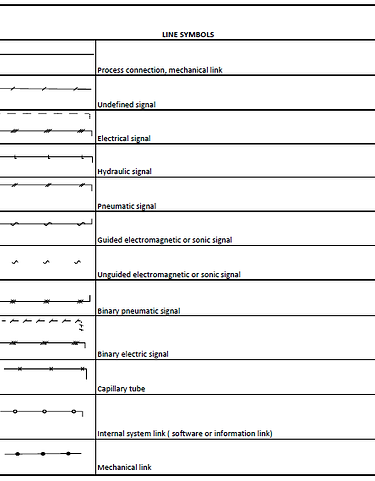
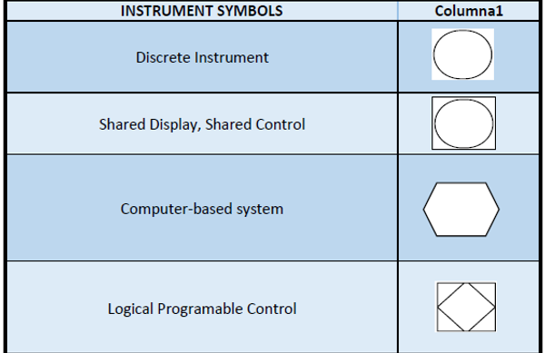
1.5 SYMBOLOGY
A lot of different norms are used to design or represent measure or control instruments. This huge variety of norms used in industrial organizations shows the universal need of a normalization in this field. Among the most important organizations for covering this topic we have ISA (Instrumentation Society of America) and the German DIN, whose norms have the objective or goal of setting application designation (code and symbols) systems.
-
Every instrument must be identified with a tag number which may contain the loop identification number, for example:
B)The number of functional letters for an instrument must be minimum, not exceeding four. For it, it is convenient:
-
Provide letter in subgroups. For example, a temperature controller with an alarm switch can be identified with two circles: TIC-3 and TSH-3
-
Letter “I” can be skipped on an instruments which indicates and records the same variable.
C)Loop numeration can be series or parallel. Parallel numeration includes a numerical sequence for each new first letter (TIC-100, FRC-100, LIC-100, etc.). Series numeration identifies instrument loops of a project with an only number sequence (TIC-100, FRC-101, LIC-102, etc.).
Simplicity is recommended.
D) If a loop has more than an instrument with the same functional identification, is better to add a suffix, like FV-2A, FV-2B, etc.
These suffixes must follow the following rules:
-
Capital letters A,B,C, etc. must be used
-
For an instrument that prints numbers for point identification, primary elements are normally numbered like TE-25-1, TE-25-2, etc.
-
Loops’ internal subdivisions can be appointed by suffixes formed by letters and numbers.
E) An instruments that does two or more functions can be appointed by all of those functions. For example, a hatch alarm for high and low temperature can be appointed by TAH/L-21
F)Accessories for instruments such as purge rotameters, filters or stamp pots which are no specifically registered in a flow diagram, but that still need and identification for other uses, must have it according to its function and they must use the same loop the associated instruments.
The following notes, indicated in Table 4.1 by parentheses, are to be used as an aid in understanding the meanings of the letters when they are used in certain positions in Loop Identification Letter(s) or Functional Identifications.
(1) First Letters are a Measured/Initiating Variable and, if required, a combination of a Measured/Initiating Variable and a Variable Modifier that shall be referred to by the combined meaning.
(2) The specific meanings given for Measured/Initiating Variables [A], [B], [E], [F], [H], [I], [J], [K] [L], [P], [Q], [R], [S], [T], [U], [V], [W], [Y], and [Z] shall not be modified.
(3) Measured/Initiating Variable analysis [A] shall be used for all types of process stream composition and physical property analysis. The type of analyzer, and for stream component analyzers the components of interest, shall be defined outside the tagging bubble.
(a) “User’s Choice” Measured/Initiating Variables [C], [D], and [M] are assigned to identify conductivity, density, and moisture analysis, respectively, when it is the user’s common practice.
(4) Measured/Initiating Variable analysis [A] shall not be used to identify vibration or other types of mechanical or machinery analysis, which shall be identified by Measured/Initiating Variable vibration or mechanical analysis [V].
(5) “User’s Choice” letters [C], [D], [M], [N], and [O] that cover unlisted repetitive meanings that may have one meaning as a Measured or Initiating Variable and another as a Succeeding-Letter shall be defined only once. For example, [N] may be defined as “modulus of elasticity” as a Measured/Initiating Variable and “oscilloscope” as a Readout/Passive Function.
(6) Measured/Initiating Variable multivariable [U] identifies an instrument or loop that requires multiple points of measurement or other inputs to generate single or multiple outputs, such as a PLC that uses multiple pressure and temperature measurements to regulate the switching of multiple on-off valves.
(7) Measured/Initiating Variable vibration or mechanical analysis [V] is intended to perform the function in machinery monitoring that Measured/Initiating Variable analysis [A] performs in process monitoring and except for vibration, it is expected that the variable of interest will be defined outside the tagging bubble.
(8) First-Letter or Succeeding-Letter for unclassified devices or functions [X] for non-repetitive meanings that are used only once or to a limited extent may have any number of meanings that shall be defined outside the tagging bubble or by a note in the document. For example, [XR-2] may be a stress recorder and [XX-4] may be a stress oscilloscope.
(9) Measured/Initiating Variable event, state, or presence [Y] is intended for use when control or monitoring responses are not driven by time or time schedule--but driven by events, presence, or state.
(10) Measured/Initiating Variable and Variable Modifier combinations shall be selected according to how the property being measured is modified or changed.
(11) Direct measured variables that shall be considered as Measured/Initiating Variables for Loop Numbering shall include but are not limited to:
(a) Differential [D] — pressure [PD] or temperature [TD].
(b) Total [Q] — flow totalizer [FQ], when directly measured, such as by a positive displacement flowmeter.
(c) X-axis, y-axis, or z-axis [X], [Y], or [Z] — vibration [VX], [VY], and [VZ], f orce [WX], [WY],or [WZ] or position [ZX], [ZY], or [ZZ].
(12) Derived or calculated from other direct measured variables that should not be considered as Measured/Initiating Variables for Loop Numbering shall include but are not limited to:
(a) Difference [D] — temperature [TD] or weight [WD].
(b) Ratio [F] — Flow [FF], pressure [PF], or temperature [TF].
(c) Time rate of change [K] — pressure [PK], temperature [TK], or weight [WK].
(13) Variable Modifier time or time schedule [K] in combination with a Measured/Initiating Variable signifies a time rate of change of the measured or initiating variable; [WK], represents a rate-of-weight- loss loop.
(14) Variable Modifier safety [S] is technically not a direct-measured variable but is used to identify self-actuated emergency protective primary and final control elements only when used in conjunction with Measured/Initiating Variables flow [F], pressure [P] or temperature [T]. And because of the critical nature of such devices, [FS, PS, and TS] shall be considered as Measured/ Initiating Variables in all Loop Identification Number construction schemes:
(a) Flow safety valve [FSV] applies to valves intended to protect against an emergency excess flow or loss of flow condition. Pressure safety valve [PSV] and temperature safety valve [TSV] apply to valves intended to protect against emergency pressure and temperature conditions. This applies regardless of whether the valve construction or mode of operation places it in the category of safety valve, relief valve, or safety relief valve.
(b) A self-actuated pressure valve that prevents operation of a fluid system at a higher-than- desired pressure by bleeding fluid from the system is a backpressure control valve [PCV], even if the valve is not intended to be used normally. However, this valve is designated a pressure safety valve [PSV] if it protects against emergency conditions hazardous to personnel and/or equipment that are not expected to arise normally.
(c) Pressure rupture disc [PSE] and fusible link [TSE] apply to all sensors or primary elements intended to protect against emergency pressure or temperature conditions.
(d) [S] shall not be used to identify Safety Instrumented Systems and components, see (30).
(15) The grammatical form of Succeeding Letter meanings shall be modified as required; for example, ‘indicate’ [I] may be read as ‘indicator’ or ‘indicating,’ and ‘transmit’ [T] may be read as ‘transmitter’ or ‘transmitting.’
(16) Readout/Passive Function glass, gauge, or viewing device [G] should be used instead of Readout/Passive Function indicate [I] for instruments or devices that provide a secondary view, such as level glasses, pressure gauges, thermometers, and flow sight glasses.
(a) Also used to identify devices that provide an uncalibrated view of plant operations, such as television monitors.
(17) Readout/Passive Function indicate [I] applies to the analog or digital readout of an actual measurement or input signal to a discrete instrument or a distributed control system's video display unit.
(a) In the case of a manual loader, it should be used for the dial or setting indication of the output signal being generated, [HIC] or [HIK].
(18) Readout/Passive Function scan [J] when used shall indicate a non-continuous periodic reading of two or more Measured/Initiating Variables of the same or different kinds, such as multipoint temperature and pressure recorders.
(19) Readout/Passive Function light [L] identifies devices or functions that are intended to indicate normal operating status, such as motor on-off or actuator position, and is not intended for alarm indication.
(20) Readout/Passive Function record [R] applies to any permanent or semi-permanent electronic or paper media storage of information or data in an easily retrievable form.
(21) Readout/Passive and Output/Active Function multifunction [U] is used to:
(a) Identify control loops that have more than the usual indicate/record and control functions.
(b) Save space on drawings by not showing tangent bubbles for each function.
(c) A note describing the multiple functions should be on the drawing if needed for clarity.
(22) Readout/Passive Function accessory [X] is intended to identify hardware and devices that do not measure or control but are required for the proper operation of instrumentation.
(23) There are differences in meaning to be considered when selecting between Output/Active Functions for control [C], switch [S], valve, damper, or louver [V], and auxiliary device [Y]:
(a) Control [C] means an automatic device or function that receives an input signal generated by a Measured/Initiating Variable and generates a variable output signal that is used to modulate or switch a valve [V] or auxiliary device [Y] at a predetermined set point for ordinary process control.
(b) Switch [S] means a device or function that connects, disconnects, or transfers one or more air, electronic, electric, or hydraulic signals, or circuits that may be manually actuated or automatically actuated directly by a Measured or Initiating Variable, or indirectly by a Measured or Initiating Variable transmitter.
(c) Valve, damper, or louver [V] means a device that modulates, switches, or turns on/off a process fluid stream after receiving an output signal generated by a controller [C], switch [S], or auxiliary device [Y].
(d) Auxiliary device [Y] means an automatic device or function actuated by a controller [C], transmitter [T], or switch [S] signal that connects, disconnects, transfers, computes, and/or converts air, electronic, electric, or hydraulic signals or circuits.
(e) The succeeding letters CV shall not be used for anything other than a self-actuated control valve.
(24) Output/Active Function control station [K] shall be used for:
(a) Designating an operator accessible control station used with an automatic controller that does not have an integral operator accessible auto-manual and/or control mode switch.
(b) Split architecture or fieldbus control devices where the controller functions are located remotely from the operator station.
(25) Output/Active Function auxiliary devices and functions [Y] include, but are not limited to, solenoid valves, relays, and computing and converting devices and functions
(26) Output/Active Function auxiliary devices [Y] for signal computing and converting when shown in a diagram or drawing shall be defined outside their bubbles with an appropriate symbol from Table 5.6 Mathematical Function Blocks and when written in text shall include a description of the mathematical function from Table 5 6.
(27) Function Modifiers high [H], low [L], and middle or intermediate [M] when applied to positions of valves and other open-close devices, are defined as follows:
(a) High [H], the valve is in or approaching the fully open position, open [O] may be used as an alternative.
(b) Low [L] the valve is in or approaching the fully closed position; closed [C] may be used as an alternative.
(c) Middle or intermediate [M] the valve is traveling or located in between the fully open or closed position.
(28) Function Modifier deviation [D] when combined with Readout/Passive Function [A] (alarm) or Output/Active Function S (switch) indicates a measured variable has deviated from a controller or other set point more than a predetermined amount.
(a) Function Modifiers high [H] or low [L] shall be added if only a positive or negative deviation, respectively, is of importance.
(29) Function Modifiers high [H], low [L], and middle or intermediate [M] when applied to alarms correspond to values of the measured variable, not to values of the alarm-actuating signal, unless otherwise noted:
(a) A high-level alarm derived from a reverse-acting level transmitter signal is an LAH, even though the alarm is actuated when the signal falls to a low value.
(b) The terms shall be used in combination as appropriate to indicate multiple levels of actuation from the same measurement, for example high [H] and high-high [HH], low [L] and low-low [LL], or high-low [HL].
(30) Variable Modifier [Z] is technically not a direct-measured variable but is used to identify the components of Safety Instrumented Systems.
(a) [Z] shall not be used to identify the safety devices noted in (14).